


Introduction
This is a user manual for Remootio Pro. If you have a Remootio 3 or Remootio 2 unit, please do not follow the steps of this manual. You can find the corresponding manuals here:

Read before use
This document contains important technical and safety information about the device, its safe use and installation.
CAUTION! Before beginning the installation, please read this guide carefully and entirely and any other documents accompanying the device and any other documents and/or webpages this document refers to. Failure to follow the installation procedures could lead to malfunction, danger to your health and life, violation of law or refusal of legal and/or commercial guarantee (if any). Remootio (Assemblabs Ltd) is not responsible for any loss or damage in case of incorrect installation or improper operation of this device due to failure of following the user and safety instructions in this guide.
Step 0 - Unboxing
Open the box and remove the Remootio device. The wires, double-sided adhesives and the sensor can be found under the removable paper insert.
Your Remootio Pro kit contains the following items:

- A - 1 x REMOOTIO PRO unit
- B - 1 x Sensor (wired part | 4m / 13.12Ft)
- C - 1 x Sensor (wireless part)
- D - 2 x Double-sided adhesives for mounting the sensor
- E - 1 x Double-sided adhesives for mounting the Remootio unit
- F - 1 x Universal power adapter base (12V)
- G - 2 x Control wire (1 m / 3.28 feet)
- H - 1 x Quickstart guide
- I - 1 x Bottom part of packaging
- J - 1 x Top part of packaging
- K - 1 x Power adapter head (depending on where you order from, the product is shipped with type A (US), type C (EU), type G (UK) or type I (AUS) head for the universal power adapter.
Read the instruction manual carefully and follow the instructions
The printed instruction manual can be found on the back side of the paper insert.

|
Before you begin, make sure that you have read this user guide carefully and entirely and that the circuit breaker of the gate or garage door (or the installation site) is switched off and there is no power in the system. |
Step 1 - Remove the plastic cover
Use a cross head screwdriver to remove the screw from the Remootio Pro unit and remove the plastic cover.

Remootio Pro pinout diagram:

|
1: Reset button |
18: Relay Output 3 – NC 19: Power input + (alternative to barrel jack) 20: Power input - (alternative to barrel jack) 21: Input 1 (IN1) (for voltage-free input device between IN1 and 12V, e.g.: push button / reed switch) 22: Input 2 (IN2) (for voltage-free input device between IN2 and 12V, e.g.: push button / reed switch) 23: 12V output 24: GND 25: Wiegand_2 D0 (for secondary wiegand device) 26: Wiegand_2 D1 (for secondary wiegand device) 27: Wiegand_1 D0 (for main wiegand device) 28: Wiegand_1 D1 (for main wiegand device) 29: Wiegand Buzzer control 30: Wiegand LED control |

Step 2 - Wiring the control output
Remootio Pro is a generic access control device. It's outputs have both NO and NC connections which makes it suitable to control:
- Group A: Motorized access control devices:
- Electric gate openers
- Garage door openers
- Electric bollards
- Barriers
- Group B: Electric Strikes / Magnetic locks:
- Power-to-lock type (fail-safe)
- Power-to-unlock type (fail-secure)
Please refer to the control output wiring chapter that corresponds to the type of device you want to control.
Connect the control output of the Remootio unit to the appropriate input terminals of your gate or garage door. In some cases there is only one input pair (single input) and in other cases there are two input pairs (dual input) on the control board that has to be triggered to open or close the gate or garage door.
2.1 Group A: Motorized access control devices
Based on the type of required control input, there are two types of gates and garage doors / motorized access controller control boards:
- A single signal (impulse) can open, stop and close the gate or garage door
- Two separate signals (impulses) needed:
- One signal for opening
- and another signal for closing.
Enter the make and model number of your gate or garage door into our compatibility checker to search for the correct wiring diagram.
Click here to access the compatibility checker
2.1.1 Single input type (1x NO output):
Use the included pair of wires to connect Remootio Pro's control output to the appropriate input terminal of your garage door / gate control board. One of the leads need to be wired to the "0V", "GND" or "COM" terminal and the other lead to "CYC", "IMPULSE", "IMP", "KBUTT", "OPERATE", "OSC", "PB", "PP", "SBS", "SS", "START", "STRT", "SW", "TRG", "WALL BUTTON" or "WALL CONTROL" depending on the manufacturer's naming convention.
(The outputs are polarity independent, which means that within the same output terminal, the order of the wires does not matter).
Please visit https://www.remootio.com/pages/compatibility and enter the make and model of your gate or garage door to search for the correct wiring diagram.
We recommend wiring the control wires into NO2 and COM2 on your Remootio Pro board.

Note: The color of the wires may be black or white.
2.1.2 Dual input type (separate input for opening and closing):
Connect Remootio's output #1 to the "open" input terminal of your gate or garage door control unit and connect Remootio's output #2 to the "close" input terminal of your gate or garage door control unit. If you have a gate or garage door opener that needs both outputs to be wired to the control board, please go to the settings menu of Remootio and select "output configuration" and please choose the "Output 1: output to open | Output 2: output to close" option.
For more details about the output configuration, please visit this article.
(The outputs are polarity independent, which means that within the same output terminal, the order of the wires does not matter).
We recommend wiring NO2 and COM2 into the Open command's terminals, and wiring NO1 and COM1 into the Close command's terminals on the control board.

2.2 Group B: Electric Strikes / Magnetic locks
There are two types devices in this group
- Power to unlock (fail-secure)
- Need to apply power to unlock the device. Stays locked when there is a power outage
- Use NO and COM terminals of the Remootio Pro when wiring
- Power to lock (fail-safe)
- Need to cut power to unluck the device. Becomes unlocked when there is a power outage
- Use NC and COM terminals of the Remootio Pro when wiring
Electric strikes can be either fail-safe or fail-secure. Magnetic locks are fail-safe by design.
2.2.1 Power to unlock (fail-secure) electric strikes
To wire Remootio Pro to a fail-secure electric strike you will need to use the NO and COM output terminals. We recommend using NO2 and COM2.
You need to connect the external power supply in a series loop with Remootio Pro's output and the strike. The basic steps are: connect power positive to COM, connect NO to the strike positive, and connect the strike negative back to power negative.

2.2.2 Power to lock (fail-safe) electric strikes and magnetic locks
To wire Remootio Pro to a fail-safe electric strike or to a magnetic lock you will need to use the NC and COM output terminals. We recommend using NC2 and COM2.
You need to connect the external power supply in a series loop with Remootio Pro's output and the strike or the magnetic lock. The basic steps are: connect power positive to NC, connect COM to the strike positive, and connect the strike negative back to power negative.


Note on the number of outputs
Remootio Pro has 3 outputs, and all of them have NO and NC connections. This means you could control up to 3 electric strikes / magnetic locks with a device.
Please be mindful though that you can only connect one status sensor (open/closed sensor) to the device.
Step 3 - Sensor installation (optional)
To know the open/closed status of your gate or other device with Remootio Pro you may:
- Use the provided wired open/close status sensor from the package
- If you are a professional installer, you may also use a signal (<24V) coming from your gate's control board (a limit switch). Make sure to carefully read the relevant section below before attempting this.
3.1 Using the wired sensor from the package
Connect the sensor to terminals IN1 and 12V or IN2 and 12V of the Remootio Pro unit and use the included adhesives to mount the wireless part of the sensor on the moving part of the gate or garage door in such a way that it is not further than 30mm from the wired part of the sensor when the gate or garage door is closed.

For more details and images about about the sensor installation, please check our sensor installation tutorial. When enabling the sensor interface in the app, please make sure to select the corresponding input ("input 1" when using IN1, and "input 2" when using IN2).
Sensor installation and use for Remootio Pro is the same as for Remootio 3, with the only difference being that when using Remootio Pro, the sensor's wires need to go into IN1 and 12V or IN2 and 12V.
3.2 Using a limit switch signal from the gate operator (<24V)
|
|
Warning: This wiring method is intended for qualified professional installers only. Attempting this installation without verifying the wiring configuration with Remootio Support and the gate operator's (garage door operator's, etc...) manufacturer may result in permanent damage to the gate / garage door opener / other equipment you are wiring, the Remootio Pro, or other connected equipment. By proceeding with this installation, you acknowledge that you do so voluntarily and at your own risk, and you accept responsibility for any damage resulting from incorrect wiring, incompatible equipment, or improper installation. |

Step 4 - Connecting keypads and card readers (optional)
Remootio Pro supports wiring up to two keypads and/or card readers that support the Wiegand protocol. We recommend using a keypad and card reader explicitly sold by or recommended by Remootio.

Remootio does not guarantee that the Remootio Pro unit will work with any arbitrary Wiegand keypad or card reader out of the box, due to the potential manufacturer-specific differences in protocol implementation.
For a detailed guide on how to set up the keypads and card readers that are sold by or recommended by Remootio please see the following article.
The terminals for connecting wiegand accessories are:
24: GND
25: Wiegand_2_D0 (for secondary wiegand device)
26: Wiegand_2 D1 (for secondary wiegand device)
27: Wiegand_1 D0 (for primary wiegand device)
28: Wiegand_1 D1 (for primary wiegand device)
29: Wiegand Buzzer control
30: Wiegand LED control
Remootio Pro supports a primary Wiegand device, and a secondary Wiegand device (2 in total). You need to wire the D0 and D1 wires of the keypad / card reader into the D0 and D1 terminals of Wiegand_1 or Wiegand_2 on the Remootio Pro. If you only have one keypad/card reader, you have to wire it into Wiegand_1 D0 and Wiegand_1 D1.
The Buzzer and LED control signals are shared between the two wiegand devices, which means both will beep and have LED feedback if either of them were used to successfully operate the gate / unlock the door.
It is important to make sure the Wiegand device is in "Wiegand reader" mode. Please refer to the user manual of the individual wiegand device to set it into reader mode.
It is important to connect the GND signal to the Wiegand device's GND terminal.
The 12V signal may be used to power the Wiegand accessories, but only as long as it does not cause interference and everything works properly. Remootio strongly recommends using a separate 12V power supply for the wiegand accessories.

- Green: D0
- White: D1
- Yellow: Buzzer control
- Brown: LED control

The image above shows how to connect two Wiegand devices to the Remootio Pro unit. Please note that the D0 (green) and D1 (white) wires of each keypad go into separate D0 and D1 inputs on the Remootio Pro. In the image above both keypads are powered from the Remootio Pro device, please keep in mind that Remootio strongly recommends to use an external 12V power supply for the wiegand devices instead.
Step 5 - Connecting other accessories (optional)
You can connect a manual control button or a doorbell button to IN1 and 12V or IN2 and 12V of the Remootio Pro. (The inputs are polarity independent, which means that within the same input terminal, the order of the wires does not matter). The doorbell or manual control button has to be a voltage-free dry-contact push button.
When configured as a manual control button, pressing the button will operate the primary output of the Remootio Pro device. You can set time limitations when the button is allowed to operate the output (Needs internet connection on the Remootio Pro)
When configured as a doorbell button from the app settings, the device will send a notification to the user's smartphone whenever someone presses the doorbell button (Remootio Pro has to be connected to the internet with EasyConnect enabled)

Step 6 - Connecting an ethernet cable (optional)
The Remootio Pro unit can connect to the internet via:
- Wi-Fi (2.4 Ghz)
- Ethernet
The Remootio Pro unit can be configured to use Wi-Fi and Ethernet at the same time. In this mode the unit will prioritize talking to the internet over Ethernet, whenever available and will use Wi-Fi as a backup.
Step 7 - Inserting a microSD card (optional)
You can insert a microSD card into the microSD card slot on the Remootio Pro device. It's recommended to insert a card with high durability and < 256 Gb storage.
A microSD card will enhance your Remootio Pro with the following features:
- Log: Activity log events are logged on the SD card (large storage space)
- Backups: You can enable backups of device settings and access rights
- Backups will be taken automatically
- You can also create a backup manually
- When you enable backups, you will be presented with a data recovery key. Note this down and save it somewhere secure, as you will need this key for some of the backup restore operations.
- You can restore previous backups
- If you reset your Remootio Pro device by accident, you can restore a backup to undo the reset (using the data recovery key)
- If you need to replace the hardware (the Remootio Pro unit) you can insert the SD card from your old unit into your new one, and restore the backup into the new device (using the data recovery key). In this case you will also need to distribute a QR code to your users to notify their apps of the physical device change. After doing this, everyone will be able to use their unique keys just the same as with the old Remootio Pro.
Step 8 - Powering Remootio Pro
Before you begin, make sure that the circuit breaker of your gate or garage door / installation location is switched off and there is no power in the system.
Remootio strongly recommends powering the device using the provided 12V power adapter, as this ensures stable and reliable operation.
Alternatively, the device may be powered using one of the other methods below provided that the power output(s) meets the required specifications and this way of powering the device does not cause interference.
8.1 Recommended: Use the included 12V power adapter to power the Remootio 3 device

The correct type of power adapter head will be included in your kit depending on where you order from. We may ship your device with one of the power adapter heads below:
- Type A (US type)
- Type C (EU type)
- Type G (UK type)
- Type I (AUS type)

8.2 Tap the power from the gate control board
Remootio Pro has a wide operating voltage range, so you can use the dedicated terminals of your gate control board to power the Remootio 3 unit.
The operating voltage range of Remootio Pro is: 12-24V DC | 12-24 VAC


8.3 External 110V/230V to 5V power adapter
Alternatively, if you don't have a wall socket near your gate or garage door and there is also no way to tap power from the gate or garage door control board, a Meanwell APV8-12 power adapter can be used:

(When installing the power adapter, please leave all previously connected wires in place and only add the blue (Neutral) and brown (Line) wires of the power adapter to the corresponding terminals. The APV 8-5 power adapter can convert 110VAC or 230 VAC to 5 Volts. Please do not install the external power adapter of Remootio unless you are a professional or you are fully knowledgeable about what you are doing.
Step 9 - Assemble the unit back together
Use a screwdriver to assemble the Remootio pro unit. Make sure that you do not damage the wires during the assembly.


Step 10 (optional) - Attach Remootio Pro to a surface
You can use the double-sided adhesives to attach Remootio to the wall of your garage or you can simply place the unit with or without using the provided adhesive inside the weatherproof plastic enclosure of your electric gate opener, or in a weatherproof junction box (outdoors), or in junction box / enclosure (indoors) or no junction box at all (indoors).

Step 11 - Download the Remootio app

Step 12 - Set up the Remootio Pro unit
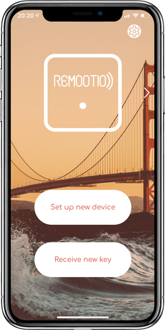
Launch the Remootio app and make sure your smartphone's Bluetooth is enabled. Tap on "Set up new device" and wait until the Remootio app finds the unit and sets it up.
When Remootio is not set up yet, it will blink approximately twice per second:

After the Remootio unit is set up successfully, Remootio will blink once every 5 seconds.

After setting up Wi-Fi or Ethernet as well, the LED on Remootio will be illuminated continuously.

Your new Remootio Pro is now ready to use. Please make sure to read the safety instructions below.
If you have any questions, please visit our FAQ page:
or let us know via e-mail at support@remootio.com
Safety instructions
Always keep the gate or garage door or barrier or bollard in sight and far away from people and objects until it is completely closed. NO ONE SHOULD CROSS THE PATH OR STAND IN THE PATH OF THE MOVING GATE OR GARAGE DOOR OR BARRIER OR BOLLARD.
The product must only be used with gate or door openers or barriers that use photoelectric sensors.
CAUTION! Danger of electrocution. Mounting/installation of the device has to be performed with caution. Make sure the circuit breaker supplying power to your gate or garage door is turned off and there is not electrical power at the site of installation before installing. If you are unsure, consult a qualified electrician.
CAUTION! Danger of electrocution. Every change in the connections has to be done after ensuring there is no voltage present at the device terminals
CAUTION! Do not use this device if it shows any sign of damage and defect
CAUTION! Do not modify the device. For safety and licensing reasons unauthorized change and/or modification of the device is not permitted.
CAUTION! Use the device only with appliances that comply with all applicable regulations. Do not connect the device to appliances exceeding the max load.
CAUTION! Connect the Device only in the way shown in these instructions. Any other method could cause injury and/or damage
CAUTION! Keep the device away from high moisture and liquids. If your device or power adaptor gets wet, carefully unplug all cables without getting your hands wet and wait for the device and adaptor to dry completely before plugging them in again. Do not attempt to dry your device or adaptor with an external heat source, such as a microwave oven or hair dryer.
CAUTION! The device can control electronic devices / electric locks / gate openers / garage door openers wirelessly. Proceed with caution! Irresponsible use of the device may lead to malfunction / danger to your life / violation of the law.
CAUTION! Only use the device with electric gate or garage door openers which comply with the relevant safety standards and legal requirements of your place of use. (Such as the ANSI/UL 325 standard or 2006/42/EC legislation) Your use of the device must also comply with these applicable laws and regulations.
Specifications
Remootio Pro device:
- Dimensions: 132mm x 55mm x 25mm / 5.197in x 2.165in x 0.984in
- Max altitude: 2000m / 6562 ft
- Ambient temperature range: -20 °C to 50 °C / -4 °F to 122 F°
- Power supply: 12V DC nominal
- Input power tolerance: 5-32V DC, 12-24V AC
- Electrical consumption: < 2W
- Max rated switching voltage: 50 VAC, 28 VDC
- Absolute maximum switching voltage tolerance: 120 VAC, 30 VDC
- Rated load: 3A at 50 VAC, 3A at 30 VDC
- Max. RF power: < 20 dBm
- Wi-Fi protocol: 802.11 b/g/n
- Wi-Fi operational range (depending on local conditions): up to 50m
- Bluetooth protocol 5.0
- Bluetooth operational range (depending on local conditions): up to 30m
Supplied power adapter (if included):
Please see ratings on the power adapter as they may be different from the ratings specified below.
- Input: 100-240V, 50/60 Hz 0.3A
- Output: 12V 1A
Please only use the power adapter to power your Remootio Pro device. Please do not use any other power adapter for powering your Remootio Pro device. If you need more information about the exact specifications of your power adapter or it's declaration of conformity please contact us at support@remootio.com or info@remootio.com
Recycling and electronic waste
In some areas, the disposal of certain electronic devices is regulated. Make sure you dispose of, or recycle, your device in accordance with your local laws and regulations.

For information about recycling your device, please see our recycling guide at https://www.remootio.com/blogs/tutorials/recycling

The use of the WEE symbol indicates that this product should not be treated as household waste. By ensuring this product is disposed of correctly, you will help protect the environment. For more detailed information about the recycling of this product, please contact your local authority, your household waste disposal service provider, or the shop where you purchased this item. This product meets all related basic EU regulation requirements. The EU declaration of conformity is available on www.remootio.com/compliance. This product sold in the European Union meets the requirements of Directive 2011/65/EU on restriction of the use of certain hazardous substances in electrical and electronic equipment (RoHS)
Declaration of conformity
Hereby, Assemblabs Ltd. declares that the radio equipment type Remootio Pro is in compliance with Directive 2014/53/EU, 2014/30/EU, 2011/65/EU. The full text of the EU declaration of conformity is avaialble at the following internet address: https://www.remootio.com/compliance
FCC warning
This device complies with part 15 of the FCC Rules. Operation is subject to the following two conditions: (1) this device may not cause harmful interference, and (2) this device must accept any interference received, including interference that may cause undesired operation. (FCC ID 2A6T6-RMT768162845)
NOTE: This equipment has been tested and found to comply with the limits for a Class B digital
device, pursuant to part 15 of the FCC Rules. These limits are designed to provide reasonableprotection against harmful interference in a residential installation. This equipment generates
uses and can radiate radio frequency energy and, if not installed and used in accordance with theinstructions, may cause harmful interference to radio communications. However, there is noguarantee that interference will not occur in a particular installation. If this equipment does
cause harmful interference to radio or television reception, which can be determined by turningthe equipment off and on, the user is encouraged to try to correct the interference by one or
more of the following measures: • Reorient or relocate the receiving antenna. • Increase the separation between the equipment and receiver. • Connect the equipment into an outlet on a circuit different from that to which the receiver is
connected. • Consult the dealer or an experienced radio/TV technician for help.
Radiation Exposure Statement
This equipment complies with FCC radiation exposure limits set forth for an uncontrolledenvironment. This equipment should be installed and operated with minimumdistance 20cmbetween the radiator and your body.
Limited warranty
The warranty for the Remootio Pro (the "Device") is provided by the entity set forth below. The provider of this warranty is sometimes referred to herein as "We". When you purchase a new Device, we warrant the Device against defects in materials and workmanship under ordinary customer use for one year (in case the applicable legal minimum warranty length is longer than one year then the applicable legal minimum warranty length) from the date of original retail purchase. During this warranty period if a defect arises in the Device, and you follow the instructions for returning the device, we will, at our option, to the extent permitted by law either (i) repair the Device using either new or refurbished parts, (ii) replace that is to be replaced, or (iii) refund to you all or part of the purchase price of the Device. This limited warranty applies, to the extent permitted by law, to any repair, replacement part or replacement device for the remainder of the original warranty period or for ninety days, whichever period is longer. All replaced parts and Devices for which a refund is given shall become our property. This limited warranty applies to only hardware components of the Device that are not subject to accident, misuse, neglect, fire or damage from other external causes, alteration, repair or commercial use.
For specific instructions about how to obtain warranty service for your Device, please contact Customers service at support@remootio.com. In general, you will need to deliver your Device in either its original packaging, or in equally protective packaging to the address specified by Customer Service. Before you deliver your Device for warranty service, it is your responsibility to back up any data you may have stored or preserved on your device. You may have to set up your device after repair from scratch using the Remootio app as if it was a brand new device.
This limited warranty gives you specific rights. You may have additional rights under applicable law, and this limited warranty does not affect such rights.
Warranty provider:
If you purchased your device from Assemblabs Ltd. (e.g.: through www.remootio.com) this warranty is provided by Assemblabs Ltd. If you purchased your device from any other reseller contact the reseller you purchased from regarding your warranty.
Security policy & Vulnerability reporting
In accordance with the EU Cyber Resilience Act (CRA) and UK PSTI requirements, the security and updates policy of the product can be accessed via our dedicated page: https://www.remootio.com/security-policy. The page also contains contact information for reporting security vulnerabilities in the product.
Notice
Manufacturer of the product: Assemblabs Kft. (Assemblabs Ltd.)
Company registration number 13 09 186675
E-mail: support@remootio.com info@remootio.com
Official website: www.remootio.com
Changes in contact information data are published by the Manufacturer on the official website.
Remootio is a trademark of Assemblabs Ltd, registered in the EU and other countries and regions.
Apple, Apple Home, Apple Watch, HomeKit and iPhone are trademarks of Apple Inc, registered in the U.S. and other countries and regions.
The Bluetooth word mark and logos are registered trademarks owned by Bluetooth SIG, Inc.
Other trademarks and trade names are those of their respective owners.
Features and specifications an appearance are subject to change without notice.
All rights to the trademark Remootio and other intellectual rights associated with this device belong to Assemblabs Kft.